What is the difference between a physical topology diagram and a logical topology diagram?
Physical shows where devices and cabling actually sit; logical shows devices, ports, and the IP addressing scheme.
The two diagrams answer different questions about the same network. The physical view is what you'd use to walk into a building and find or fix the hardware — it tells a technician which rack, room, and cable to look at. The logical view is what you'd use to understand how traffic flows and is addressed — it shows how devices are connected in terms of ports and IP addresses, regardless of where the boxes physically sit. You typically need both: one to troubleshoot the wiring, the other to troubleshoot the addressing.
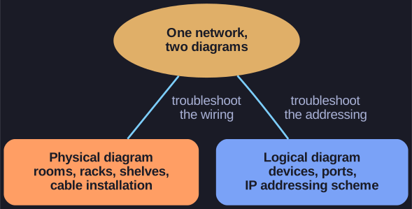
* Same network, two diagrams: the physical view to fix the wiring, the logical view to reason about addressing. *
-
Physical topology diagram: Shows the physical location of intermediary devices and cable installation (rooms, racks, shelves)
-
Logical topology diagram: Shows devices, ports, and the IP addressing scheme of the network
Important terms:
- NIC (Network Interface Card): hardware that connects a device to the network
- Physical Port: Connector on a device
- Interface: Specialized ports on network devices (port and interface are often used interchangeably)
Go deeper:
 Logical vs. physical topology: What's the difference? (TechTarget) — directly contrasts the two diagram types (physical layout/cabling vs. data-flow paths) with a clear analogy.
- Network topology (Wikipedia) — physical topology (device/cable placement) vs. logical topology (how data flows), with the classic star-physical/bus-logical Ethernet example.